
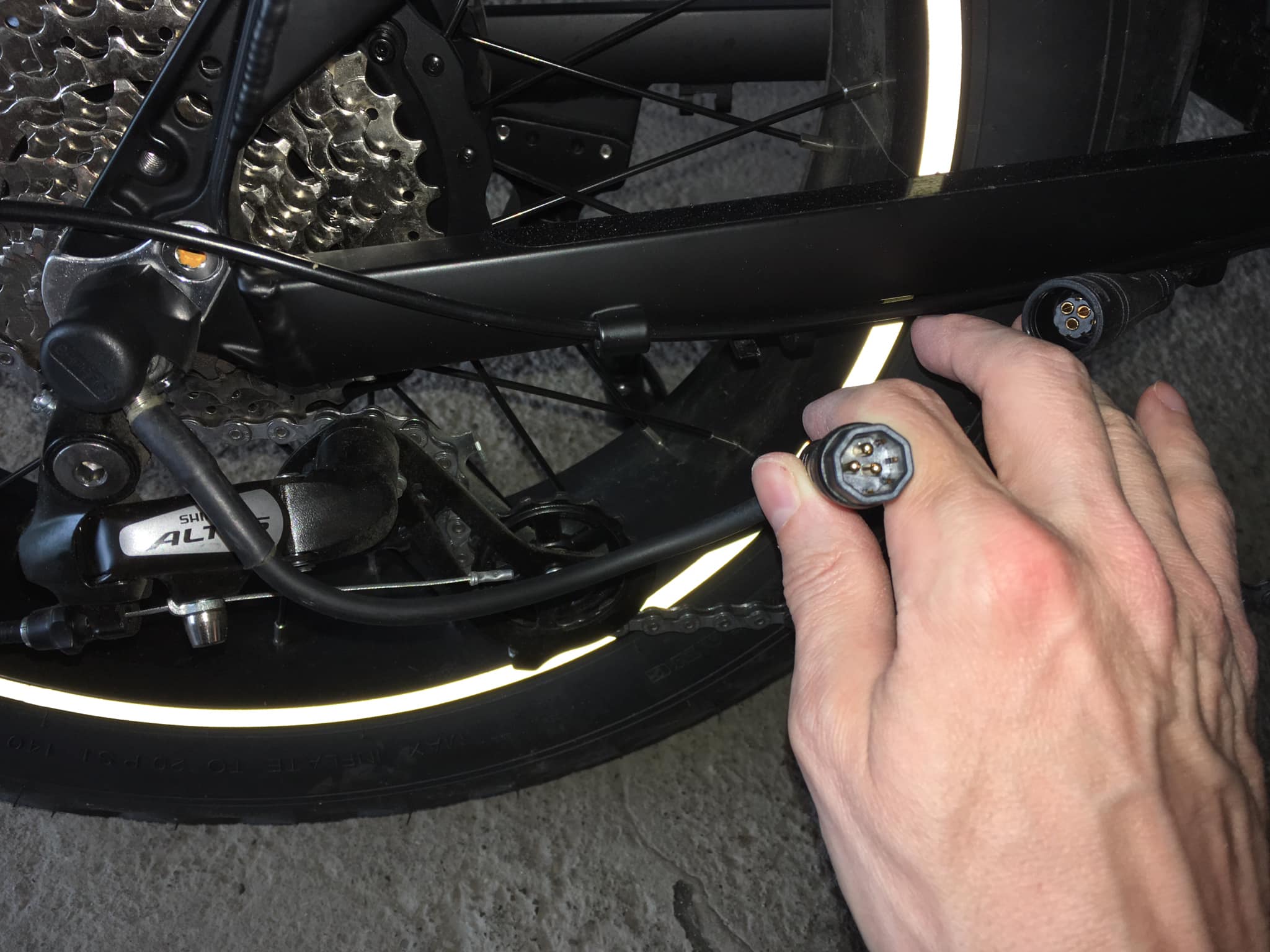
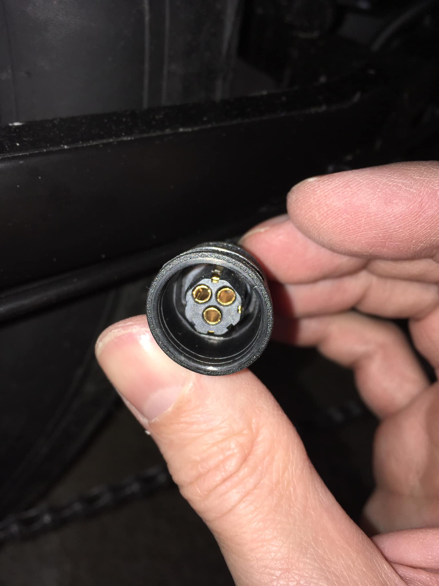
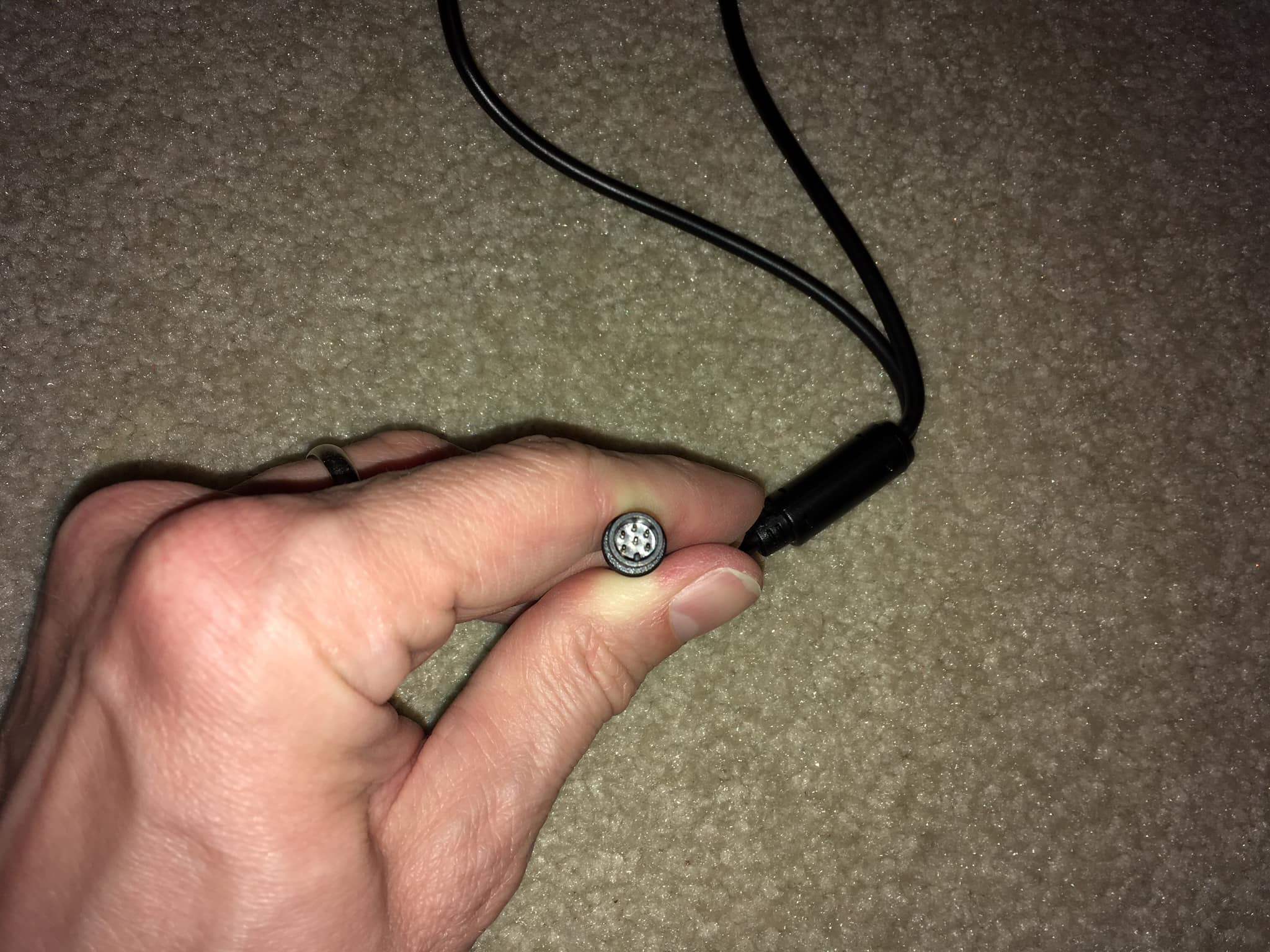
Lead from motor with lead from controller in background. 
Close up motor female connector from controller 
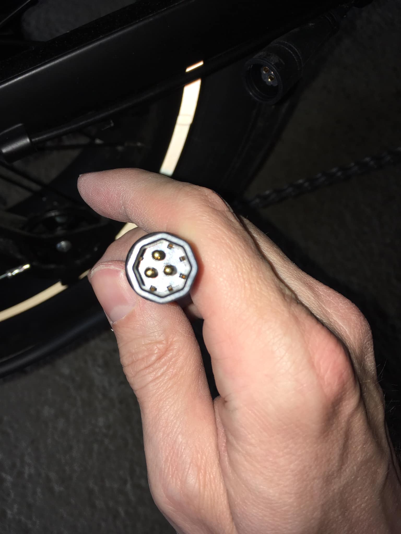
Close up male lead from motor 
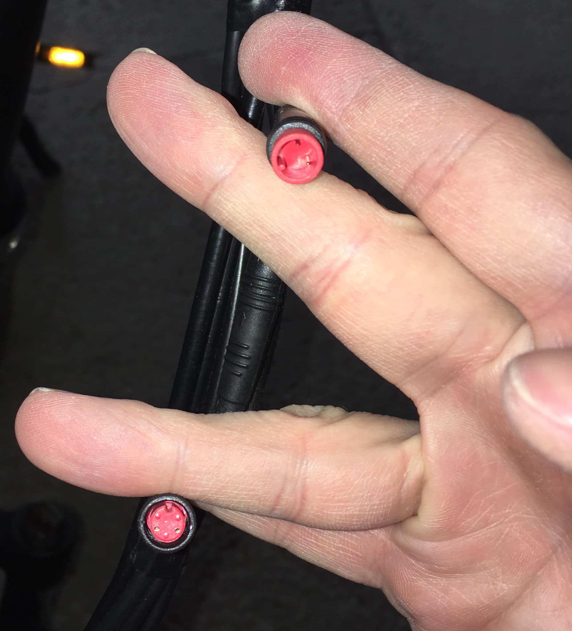
Two-prong male lead from front brake lever along with two-prong female lead from controller. Female has three raised dots to differentiate from rear brake connectors since they are both red. 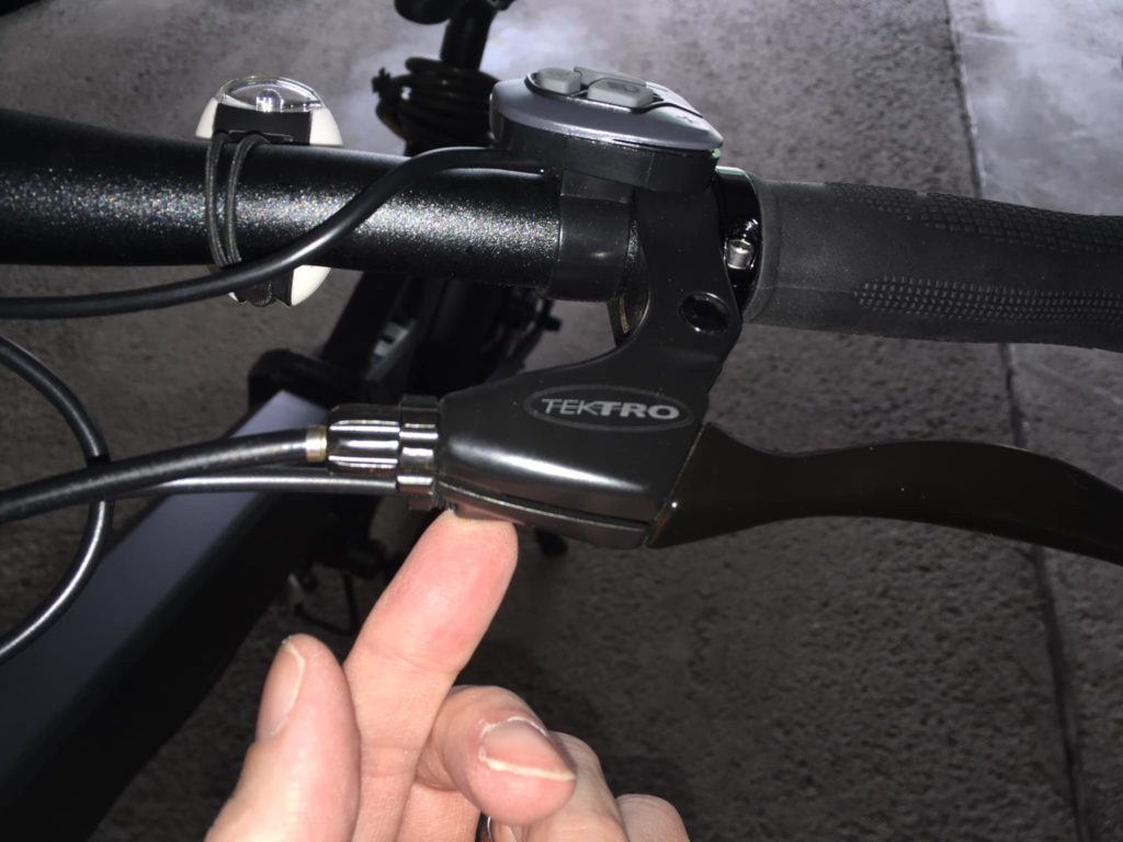
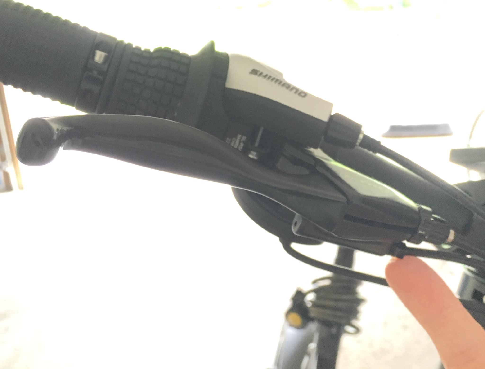
Front brake wire. 
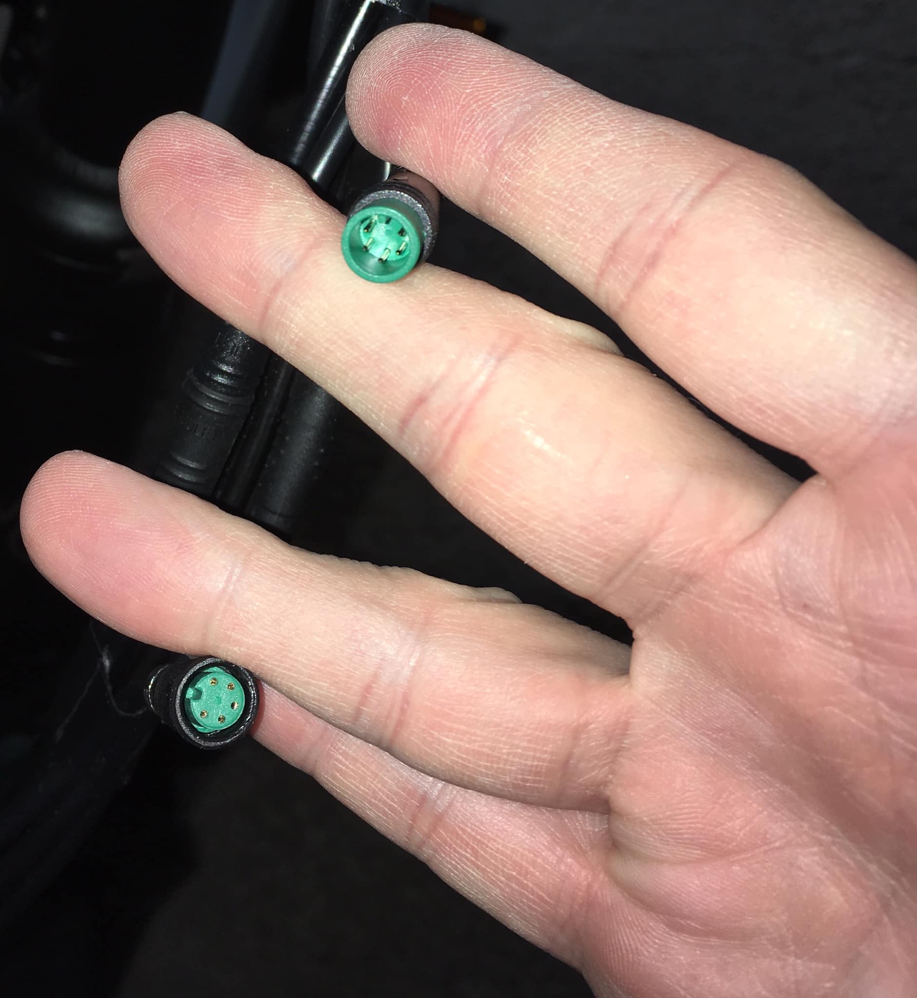
Five-prong male lead from display to female lead to controller. Green. 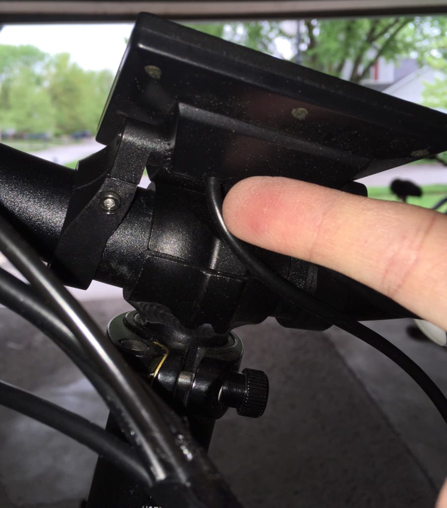
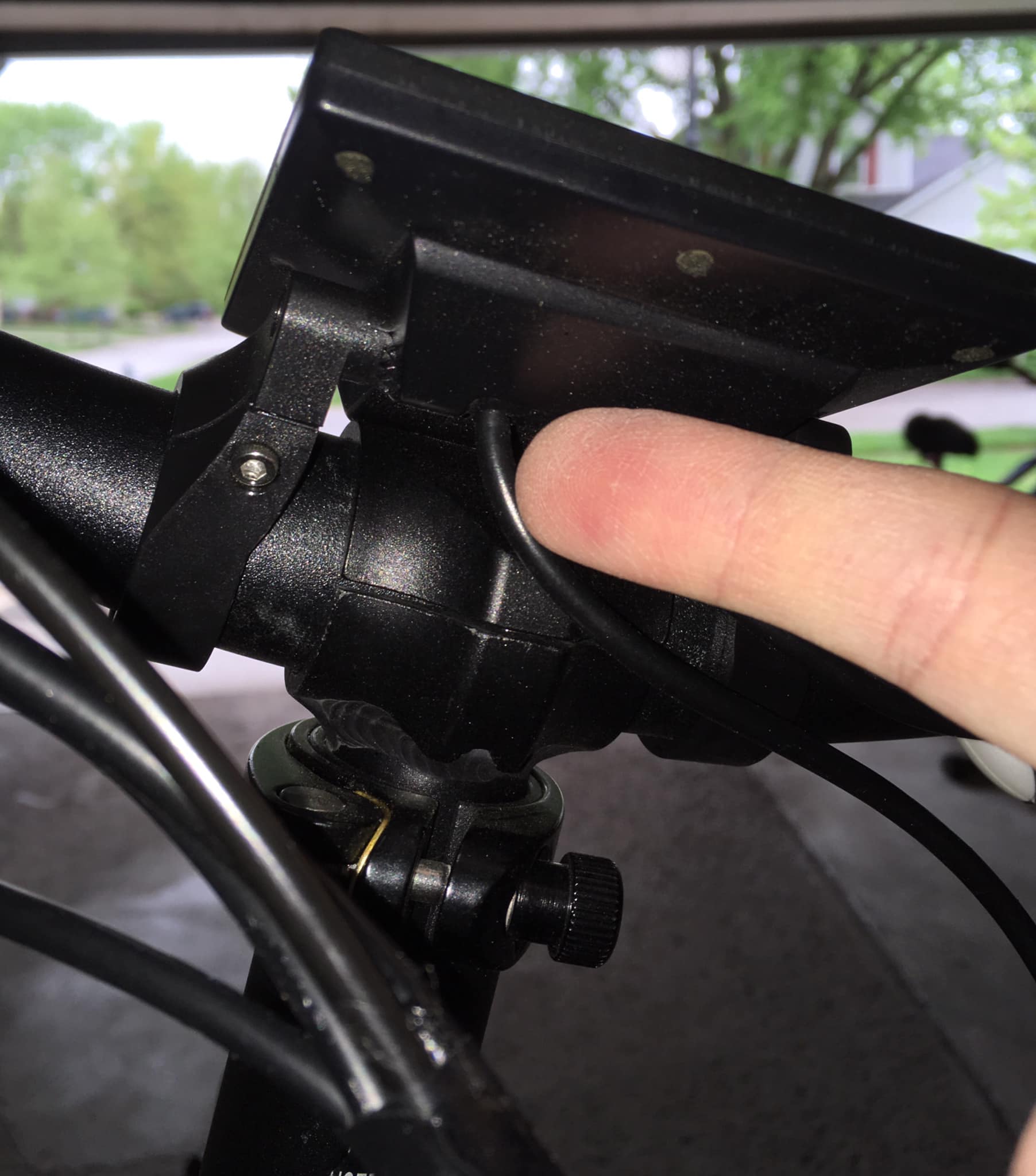
Wire to display. 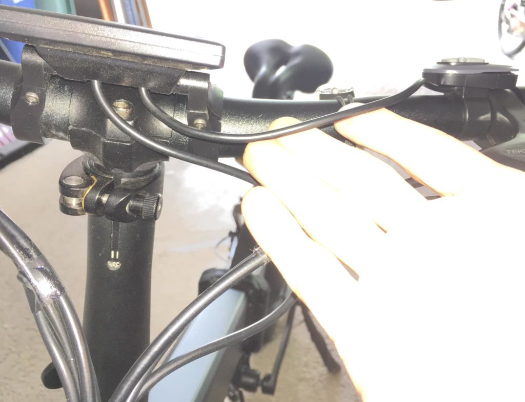
Just showing that the remote display buttons are hard-wired to the display 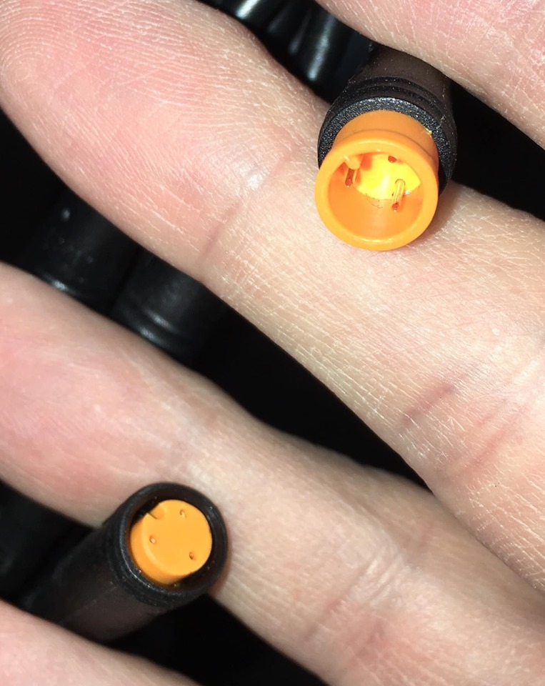
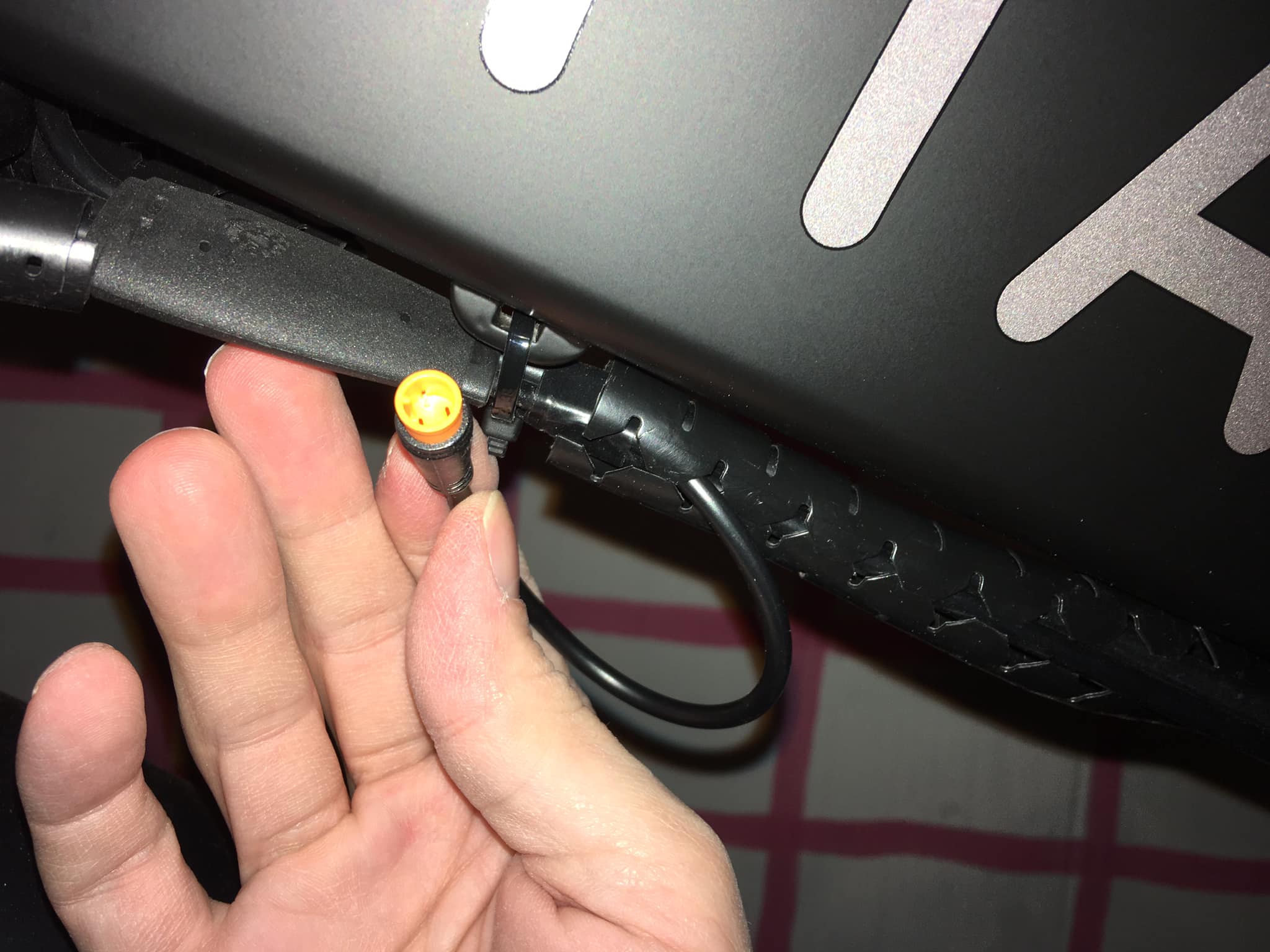
Three-prong male lead to throttle and female lead to controller. Yellow. 
Wire to throttle. 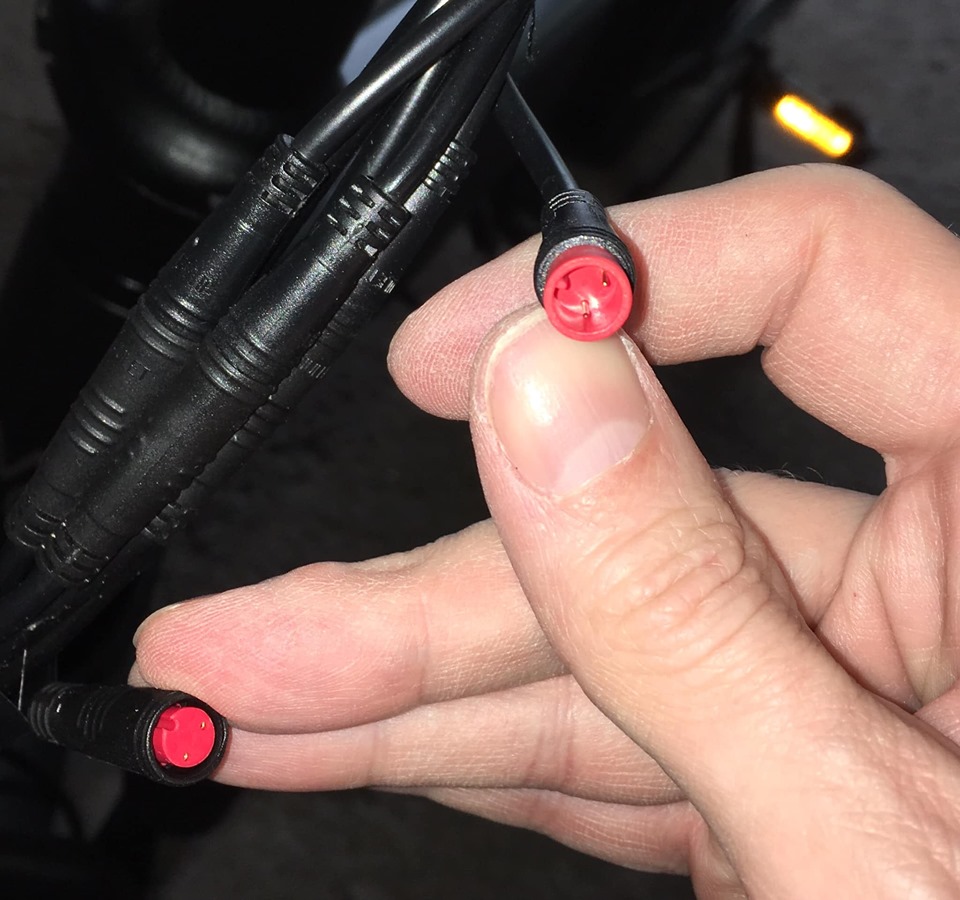
Two-prong male lead to rear brake lever as well as female lead to controller. Red, but without the three raised dots on the female. 
Wire to rear brake lever. This is used to kill the motor power as well as for the brake light. 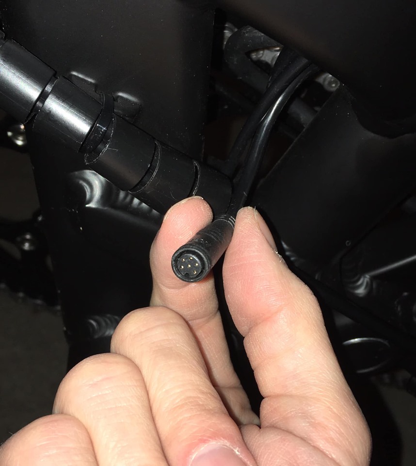
Six pin female connector coming from controller for rear light/turn signals. This is tucked up inside the controller compartment where all the cables come out of the frame. Connects to the black T connector cable that has two green five-pin connectors (one male and one female). You won’t use this unless you purchased the front light, and rear light/turn signal option. Black. 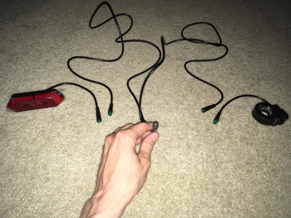
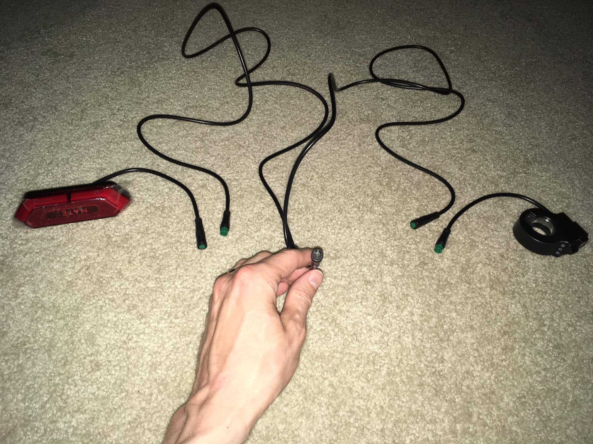
Overall view of turn signal / rear light, and turn signal switch / horn button. 
Six pin male connector that attaches to short cable from controller for turn signals, brake light, and horn. 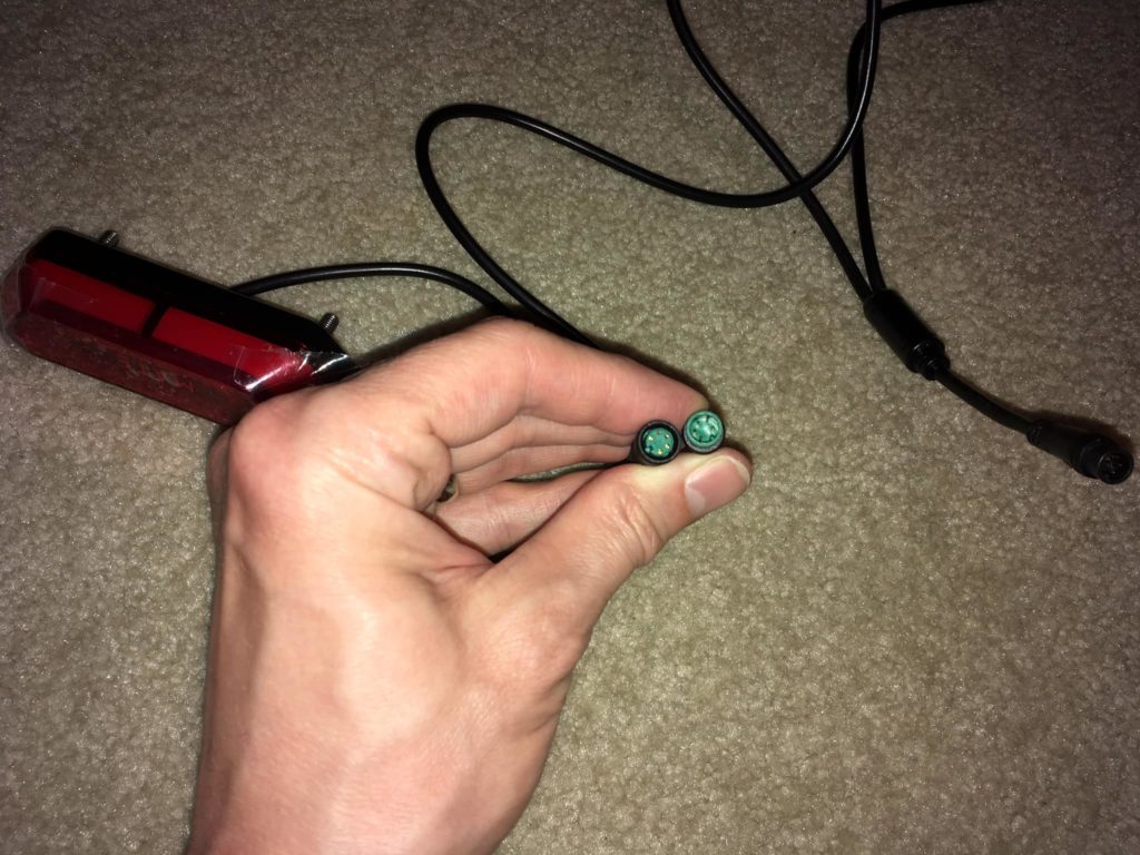
Five pin female connector for brake light / tail light / turn signals with five pin male connector that merges with turn signal switch / horn button cable. Green. 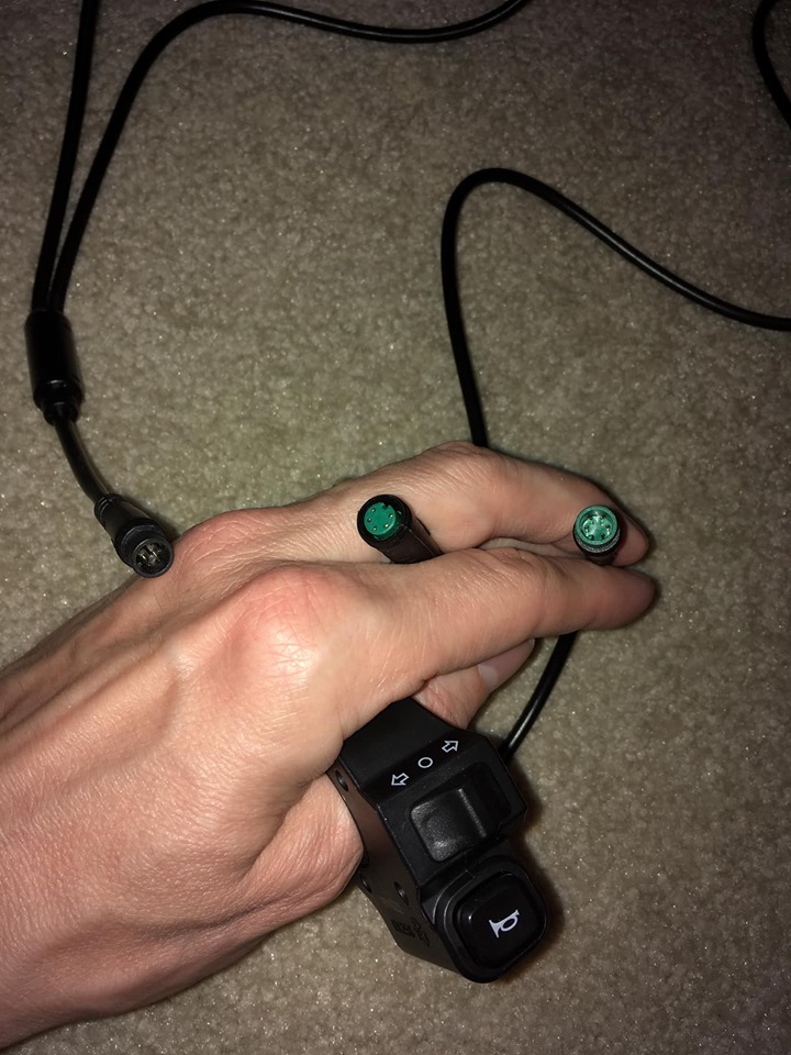
Five pin male connector attached to turn signal and horn button with five pin female connector that merges with taillight wire. Green. 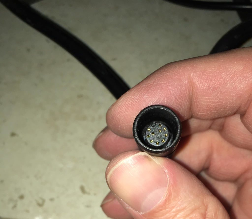
10-pin female connector from controller that connects to main connector (which splits off into four connectors; front brake lever, rear brake lever, throttle, display/controls). 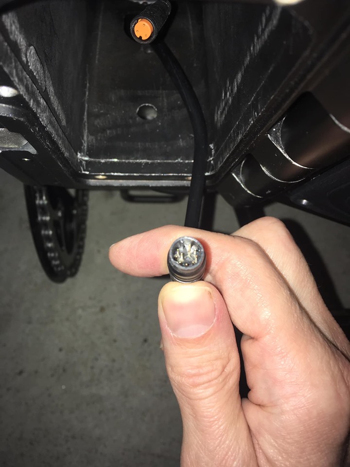
10-pin male connector that splits off into four connectors; front brake lever, rear brake lever, throttle, display/controls. (FYI the yellow connector in the background is for cadence sensor) 
This is a yellow three-prong male connector that was stowed unused in the wiring guide. This connects to the front light/horn. 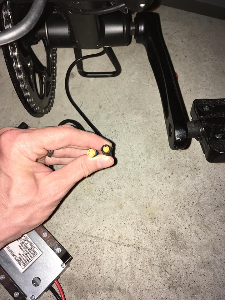
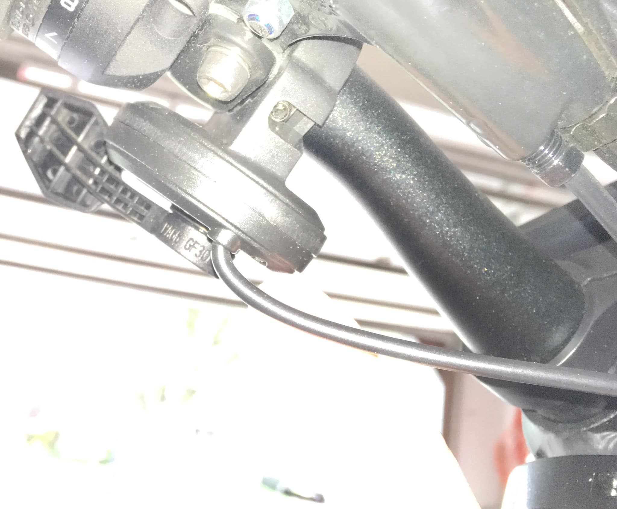
Female three-prong connector to cadence sensor on left pedal crank along with three-prong male connector going to controller. 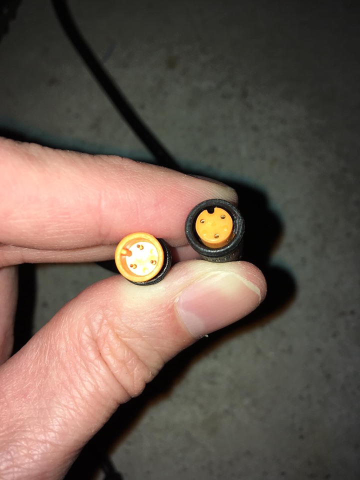
Close up of female three-prong connector to cadence sensor on left pedal crank along with three-prong male connector going to controller. 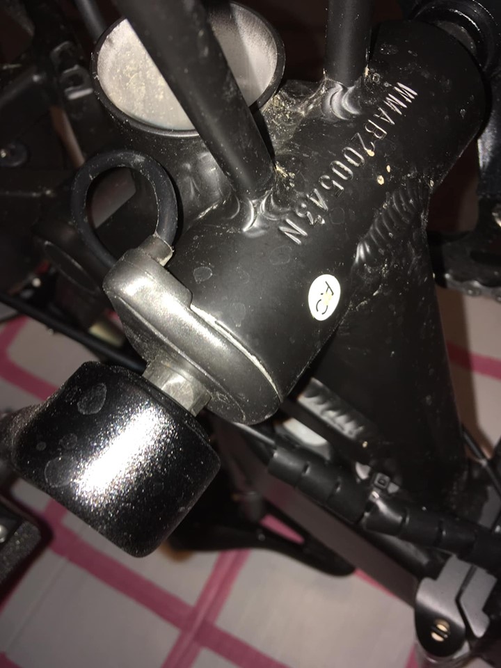
Wire attached to cadence sensor on left pedal crank. This is the wire with the yellow female three-prong connector. 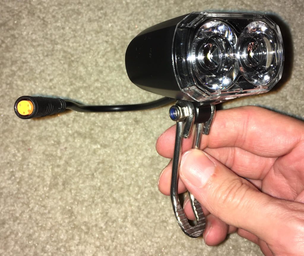
Yellow three prong female connector for front light/horn. This attaches to the yellow three prong male connector that is stowed in the wiring guide under the T in the MATE logo.


credits: Jason D. original post
You can buy some of these cables on Amazon or AliExpress: